Archiv der Kategorie: Raspberry Pi

A Matrix Keypad on a Raspberry Pi done right

There are quite a few articles to be found on the Internet on how to use a matrix keyboard on a Raspberry Pi.

Surprisingly none of them seems to use the method documented here.

Instead most of them seem to use some handcrafted Raspberry Pi and python-only solution with debounce logic implemented in userland.

As with my article on Setting up a GPIO-Button “keyboard” on a Raspberry Pi this uses a device tree based approach and will not require any driver code in userland.

As with the solution above an application will be able to use this keyboard just in the same way as any other keyboard (e.g. a standard USB keyboard) connected to a computer running Linux.

So here is how to do it:

To check if the driver is available modinfo matrix-keypad should show you something like this:

pi@raspberrypi:~$ sudo modinfo matrix-keypad
alias:          platform:matrix-keypad
license:        GPL v2
description:    GPIO Driven Matrix Keypad Driver
author:         Marek Vasut <marek.vasut@gmail.com>
srcversion:     54E6656500995BD553F6CA4
alias:          of:N*T*Cgpio-matrix-keypadC*
alias:          of:N*T*Cgpio-matrix-keypad
depends:        matrix-keymap
intree:         Y
vermagic:       4.9.35+ mod_unload modversions ARMv6 p2v8 
</marek.vasut@gmail.com>

To enable the driver we need to create a device tree overlay file suitable for a given matrix keyboard.

As an example I use the following device available at your favorite china shop.

4x5matrix

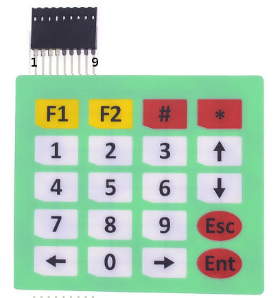
Here is what the corresponding device tree overlay file 4x5matrix.dts looks like:

    /dts-v1/;
    /plugin/;
    / {
           compatible = "brcm,bcm2835", "brcm,bcm2708", "brcm,bcm2709";

           fragment@0 {
              target-path = "/";
              __overlay__ {
                 keypad: MATRIX4x5 {
                    compatible = "gpio-matrix-keypad";
                    debounce-delay-ms = <10>;
                    col-scan-delay-us = <10>;
                    /* 
		       try to use GPIO only lines
                       to keep SPI and I2C usable
                    */
                    row-gpios = <&gpio 27 0    // 1
                                 &gpio 22 0    // 2
                                 &gpio 10 0    // 3
                                 &gpio 9 0>;   // 4

                    col-gpios = <&gpio 13 0    // 5
                                 &gpio 26 0    // 6
                                 &gpio 16 0    // 7
                                 &gpio 20 0    // 8
                                 &gpio 21 0>;  // 9
                    /*
                      Keycodes from /usr/include/linux/input-event-codes.h
                      converted to hex using printf '%02x\n'
                    */

                    linux,keymap = <
                                    // col0 row0 KEY_LEFT
                                    0x00000069
                                    // col0 row1 KEY_KP0
                                    0x01000052
                                    // col0 row2 KEY_RIGHT
                                    0x0200006a
                                    // col0 row3 KEY_KPENTER
                                    0x03000060
				    // col1 row0 KEY_KP7
                                    0x00010047
                                    // col1 row1 KEY_KP8
                                    0x01010048
                                    // col1 row2 KEY_KP9
                                    0x02010049
                                    // col1 row3 KEY_ESC
                                    0x03010001
                                    // col2 row0 KEY_KP4
                                    0x0002004b
                                    // col2 row1 KEY_KP5
                                    0x0102004c
                                    // col2 row2 KEY_KP6
                                    0x0202004d
                                    // col2 row3 KEY_DOWN
                                    0x0302006c
                                    // col3 row0 KEY_KP1
                                    0x0003004f
                                    // col3 row1 KEY_KP2
                                    0x01030050
                                    // col3 row2 KEY_KP3
                                    0x02030051
                                    // col3 row3 KEY_UP
                                    0x03030067
                                    // col4 row0 KEY_F1
                                    0x0004003b
                                    // col4 row1 KEY_F2
                                    0x0104003c
                                    // col4 row2 KEY_KPSLASH there is no KP_#
                                    0x02040062
                                    // col4 row3 KEY_KPASTERISK
                                    0x03040037>;

                 };
              };
           };
      };

Further documentation can be found in the file Documentation/devicetree/bindings/input/matrix-keymap.txt inside the Linux kernel source tree. Feel free to ask if it does not work for you.

Now to enable our keyboard there are only four steps left:

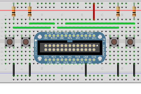
  1. Connect the keyboard to the GPIO lines as defined in the dts file
  2. Compile the dts file to the binary dtbo format. This is done using the device tree compiler of your kernel tree:
    ./scripts/dtc/dtc -W no-unit_address_vs_reg -I dts -O dtb -o 4x5matrix.dtbo 4x5matrix.dts
    
  3. Copy the resulting dtbo file to /boot/overlays/4x5matrix.dtbo on the Raspberry Pi
  4. Add the following to /boot/config.txt:
    dtoverlay=4x5matrix
    

Now after rebooting the Pi the lsinput command should show us a new keyboard connected to the device. You may need to install a package called input-utils first if this command ist not available on your Pi.

Here is what this looks like after pressing the Enter Key on the matrix keyboard:

pi@raspberrypi:~$ sudo -s
root@raspberrypi:~# lsinput
/dev/input/event0
   bustype : BUS_HOST
   vendor  : 0x0
   product : 0x0
   version : 0
   name    : "MATRIX4x5"
   bits ev : EV_SYN EV_KEY EV_MSC EV_REP

root@raspberrypi:~# input-events 0
/dev/input/event0
   bustype : BUS_HOST
   vendor  : 0x0
   product : 0x0
   version : 0
   name    : "MATRIX4x5"
   bits ev : EV_SYN EV_KEY EV_MSC EV_REP

waiting for events
19:56:28.727096: EV_MSC MSC_SCAN 24
19:56:28.727096: EV_KEY KEY_KPENTER (0x60) pressed
19:56:28.727096: EV_SYN code=0 value=0
19:56:28.797104: EV_MSC MSC_SCAN 24
19:56:28.797104: EV_KEY KEY_KPENTER (0x60) released
19:56:28.797104: EV_SYN code=0 value=0

Happy hacking!

Setting up a GPIO-Button „keyboard“ on a Raspberry Pi

 
Update: If you need more than a hand full of buttons you might be better of using a matrix keyboard instead.

Back in late 2013, when I wrote the first Version of a raspberry-pi based software controlling a HD44780 based 4×20 characters LCD and 4 input buttons I started querying the buttons using the generic GPIO driver included in Raspbian and its sysfs interface.

However, this has a couple of drawbacks. First of all it is hardly portable to other Linux based hardware and one has to do a lot of stuff like debouncing on the application level.

Fast forward to early 2017. Raspbian now uses a device-tree based approach for system setup and a driver called gpio-keys is readily available in its standard kernel.

However, as it is often the case in the Free Software world, the documentation of this driver is limited to some README files included in the Linux kernel and some discussions scattered all around the web.

Linux already has drivers for almost all of the common low level peripheral interfaces like I2C, SPI, OneWire, hardware PWM and generic GPIO. It is usually the better approach to use them instead of constantly re-inventing the wheel.

So here is my quick guide for setting up a „keyboard“ made up from a couple of buttons connected via GPIO ports as shown in the image.

gpio-keys

While this has currently only been tested on Raspberry Pi, it will likely also work on other Linux based boards with device tree enabled (e.g Beaglebone and others).

Keyboards in modern Linux Kernels are presented to userland as a so called input event device. To inspect them I would recommend the installation of the evtest and input-utils packages on Debian/Ubuntu based distributions. The lsinput command (run as root) shows which ones are available on a system.

So, what do we need to do to make a keyboard from our GPIO connected push-buttons?

The missing link between the gpio-keys driver and the setup of the actual GPIO ports, where the buttons are connected to, is a so called device-tree (DT) overlay.

While DT itself is a data structure for describing hardware, a DT overlay is something a user can put in place to change such a hardware description in a way which matches the actual application scenario (like buttons, buses etc. connected to the device).

So let’s build such an overlay for the four buttons shown in our schematic above.
The Documentation available at raspberrypi.org provides some clues about device tree overlays as well.

Here is the final result which works, so let’s go into the details:

    /dts-v1/;
    /plugin/;
    / {
       compatible = "brcm,bcm2835", "brcm,bcm2708", "brcm,bcm2709";
       
       fragment@0 {
          target-path = "/";
          __overlay__ {
             keypad: breadboard_keys {
                compatible = "gpio-keys";
                #address-cells = <1>;
                #size-cells = <0>;
		autorepeat;
                button@22 {
                   label = "breadboard Menu";
                   linux,code = <28>;
                   gpios = <&gpio 22 1>;
                };
                button@10 {
                   label = "breadboard down";
                   linux,code = <108>;
                   gpios = <&gpio 10 1>;
                };
                button@9 {
                   label = "breadboard up";
                   linux,code = <103>;
                   gpios = <&gpio 9 1>;
                };
                button@11 {
                   label = "breadboard enter";
                   linux,code = <14>;
                   gpios = <&gpio 11 1>;
                };
             };
          };
       };
    };

Our overlay fragment contains a keypad called breadboard_keys. This is actually the string which lsinput will show as the actual name of our input device. 22, 10, 9 and 11 are the GPIO port numbers corresponding to the green wires in our schematic.

The file gpio-keys.txt from the Linux Kernel source-tree will show us what our four button definitions need to look like. We need a label, which is arbitrary text, a linux,code which is actually a keycode as defined in /usr/include/linux/input-event-codes.h and we need a gpio definition with two options, the number of the GPIO to use and a boolean value indicating if the button is active low (1, as in our case) or active high (0).

Another thing I would like to point at is the autorepeat keyword. If given this will activate a key-press repeat behavior known from ordinary keyboards. The production of key-press-events will be repeated as long as the button is pressed.

Now how to enable this overlay on Raspberry Pi?
Very simple, once you know how 🙂

First put the above code in a file e.g. breadboard.dts.

Then compile a binary version and put it into the right place:
dtc -I dts -O dtb -o /boot/overlays/breadboard.dtbo breadboard.dts

Finally the following line must be added to /boot/config.txt:
dtoverlay=breadboard

Now we are done.

Here is how this looks like on the software side without any other input devices like keyboards connected:

root@raspberrypi:~# lsinput
/dev/input/event0
   bustype : BUS_HOST
   vendor  : 0x1
   product : 0x1
   version : 256
   name    : "breadboard_keys"
   phys    : "gpio-keys/input0"
   bits ev : EV_SYN EV_KEY EV_REP

root@raspberrypi:~# input-events 0
/dev/input/event0
   bustype : BUS_HOST
   vendor  : 0x1
   product : 0x1
   version : 256
   name    : "breadboard_keys"
   phys    : "gpio-keys/input0"
   bits ev : EV_SYN EV_KEY EV_REP

waiting for events
20:00:23.629190: EV_KEY KEY_BACKSPACE (0xe) pressed
20:00:23.629190: EV_SYN code=0 value=0
20:00:23.749163: EV_KEY KEY_BACKSPACE (0xe) released
20:00:23.749163: EV_SYN code=0 value=0
20:00:23.969176: EV_KEY KEY_DOWN (0x6c) pressed
20:00:23.969176: EV_SYN code=0 value=0
20:00:24.099151: EV_KEY KEY_DOWN (0x6c) released
20:00:24.099151: EV_SYN code=0 value=0
20:00:24.329158: EV_KEY KEY_UP (0x67) pressed
20:00:24.329158: EV_SYN code=0 value=0
20:00:24.439154: EV_KEY KEY_UP (0x67) released
20:00:24.439154: EV_SYN code=0 value=0
20:00:24.669157: EV_KEY KEY_ENTER (0x1c) pressed
20:00:24.669157: EV_SYN code=0 value=0
20:00:24.759176: EV_KEY KEY_ENTER (0x1c) released
20:00:24.759176: EV_SYN code=0 value=0
root@raspberrypi:~# grep breadboard /sys/kernel/debug/gpio
 gpio-9   (                    |breadboard up       ) in  hi    
 gpio-10  (                    |breadboard down     ) in  hi    
 gpio-11  (                    |breadboard enter    ) in  hi    
 gpio-22  (                    |breadboard Menu     ) in  hi    

Finally something which is not strictly on-topic concerning this post. There is something one should know about keyboard like input event devices like this. Pressing a button will send events to all applications normally consuming them (e.g. applications running on Linux console or X-Window system).

This might be an unwanted behavior. If so, your application software needs to issue a EVIOCGRAB ioctl after opening the input device.

A Raspbian read-only root-fs HOWTO

In embedded applications it is often a requirement, that the device must be able to sustain a power cycle almost any time.

Unfortunately this is not something which modern operating systems (including GNU/Linux) like very much.

Fortunately in Linux there are workarounds. While there are specialized filesystems like f2fs, the most simple approach is still to just run the OS from a read-only root filesystem.

So here is the solution I made for my brewing hardware.

We bootup our fresh raspbian image install available at http://downloads.raspberrypi.org.

On the HDMI console expand the filesystem and setup i18n (german keyboard in my case).

All steps starting from here can now be done via ssh as well as the HDMI console.

  • Remove some stuff which is not needed or unsuitable for readonly operation:
  • apt-get remove --purge wolfram-engine triggerhappy
    apt-get remove --purge cron anacron logrotate dbus dphys-swapfile
    
  • Remove X-Server and related stuff:
  • apt-get remove --purge xserver-common lightdm
    insserv -r x11-common
    
  • auto-remove some X11 related libs
  • apt-get autoremove --purge
    
  • Install busybox syslog instead of rsyslog
  • The reason for doing this is because we do not want logfiles, but we want to be able to do some debugging (read logfiles). busybox-syslogd does not write logfiles but logs to a ring-buffer in memory which can be displayed using the logread command:

    apt-get install busybox-syslogd
    dpkg --purge rsyslog
    

The following steps are important, because we do not want any filesystem checks on our headless system at all!

  • Comment do_start in /etc/init.d/checkroot.sh
  • Comment do_start in /etc/init.d/checkfs.sh
  • ...
    case "$1" in
      start|"")
            #do_start
            ;;       
      restart|reload|force-reload)
            echo "Error: argument '$1' not supported" >&2
            exit 3
            ;;    
      stop)
            # No-op
            ;;     
      *)
            echo "Usage: checkfs.sh [start|stop]" >&2
            exit 3
            ;;    
    esac
    ...
    
  • Comment Operations in /etc/init.d/checkroot-bootclean.sh
  • ...
    case "$1" in
      start|"") 
            # Clean /tmp, /lib/init/rw, /run and /run/lock.  Remove the
            # .clean files to force initial cleaning.  This is intended
            # to
            # allow cleaning of directories masked by mounts while the
            # system was previously running, which would otherwise
            # prevent
            # them being cleaned.
            #rm -f /tmp/.clean /lib/init/rw/.clean /run/.clean /run/lock/.clean
    
            #clean_all
            exit $?   
            ;;
      restart|reload|force-reload)
            echo "Error: argument '$1' not supported" >&2
            exit 3
            ;;
      stop)   
            # No-op
            ;;
      *)
            echo "Usage: checkroot-bootclean.sh [start|stop]" >&2
            exit 3
            ;;
    esac
    ...
    
  • Comment swaponagain ’swapfile‘ in /etc/init.d/mountall.sh
  • Remove a couple of startup scripts:
  • insserv -r bootlogs
    insserv -r sudo
    insserv -r alsa-utils
    insserv -r console-setup
    insserv -r fake-hwclock 
    
  • Change /etc/fstab as follows:
  • proc              /proc           proc    defaults     0       0
    /dev/mmcblk0p1    /boot           vfat    defaults,ro  0       2
    /dev/mmcblk0p2    /               ext4    defaults,ro  0       1
    tmpfs             /tmp            tmpfs   defaults     0       0
    
  • append ro in /boot/cmdline.txt:
  • ...  elevator=deadline rootwait ro
    
  • Make dhclient write its leases file to /tmp instead of /var/lib/dhcp/:
  • rm -rf /var/lib/dhcp/
    ln -s /tmp /var/lib/dhcp
    

That’s it, have fun with your read-only Raspbian. As far as my brewing software is concerned, there is automated remount-rw/ro support included (see sample configfile).

4 different Methods of 1-wire access on Raspberry Pi

1-Wire is a bus-system commonly used for temperature sensors. However, there are many more 1-wire devices than just temperature sensors.owfs has been my Linux software of choice for accessing this bus for many years now. As you might have guessed I mainly use it for my brewing software.

While Raspberry Pi does not have a native 1-wire Interface it is still quite easy to connect 1-wire devices to your Pi.

AFAIK, there are 4 methods for connecting 1-wire devices to Raspberry Pi, here are they with their pros and cons.

Method

pros

cons

notes

1. w1-gpio kernel driver

  • most simple interface, just a pullup-resistor needed
  • driver broken in standard Raspbian Kernel
  • unsuitable for large bus lengths
  • owserver needs root privileges
to make this work on a standard raspbian kernel manually apply this patch.
The following stable kernels already include the fix:
≥ 3.0.70
≥3.2.41
≥3.4.37
≥ 3.8.4
≥ 3.9.0

University of Cambridge Computer Laboratory has a nice tutorial on the non-owfs related part.

2. I2C Busmaster (DS2482-X, DS2483)

  • simple 1-chip solution using I2C bus
  • optional galvanic insulation of 1-wire-bus using I2C isolator (e.g. ADUM1250)
  • SMD soldering required
I only tested the DS2483, which is a 3.3V/5V device.
If the owfs-version from Raspbian wheezy is used, the --no_PPM option is needed.
Schematics including the ADUM1250 I2C-isolator are available at my RaspIO Webpage.

3. DS2480B Busmaster on serial port


  • 3.3V/5V level shifter recommended
  • occupies the only serial port available.
  • SMD soldering required
4. DS9490R/DS2490 USB Busmaster

  • In case of DS9490R no soldering required
  • hardware is discontinued
  • occupies one of the two available USB ports
  • To workaround power supply problems an USB-hub might be required

I tend to recommend the I2C solution if more than just a temperature sensor with a short wire is required.